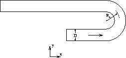
This section is concerned with the application of the present method to the prediction of flow through a sharp two-dimensional U-bend as shown in Figure 4.25.
Such a flow occurs for example in cooling passages within gas-turbine blades. Earlier numerical studies were made by e.g. Choi et al. (1989) and Bo and Iacovides (1993). We compare our results with numerical results from Bo et al. and experimental data taken from [Bo and Iacovides, 1993].
The bend geometry considered here has a curvature ratio  , which
causes separation. Here D is the width of the duct. The Reynolds number based on
the duct width and the centerline inflow velocity
, which
causes separation. Here D is the width of the duct. The Reynolds number based on
the duct width and the centerline inflow velocity  is 100,000. The inflow
boundary is located at three duct widths upstream of the bend, whereas the outflow
is specified at eight duct widths downstream of the bend. At smooth walls, the
wall functions are applied. The streamwise velocity at inflow is described
according to the power-law profile with n = 7, whereas k and
is 100,000. The inflow
boundary is located at three duct widths upstream of the bend, whereas the outflow
is specified at eight duct widths downstream of the bend. At smooth walls, the
wall functions are applied. The streamwise velocity at inflow is described
according to the power-law profile with n = 7, whereas k and  are
obtained from the formula (4.3). Here, the turbulence intensity is taken
to be 6% (in accordance with the experiment) and
are
obtained from the formula (4.3). Here, the turbulence intensity is taken
to be 6% (in accordance with the experiment) and 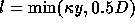 .
.
First, computations were performed to examine the grid dependence of the
solutions. To this end, three grids of 50x30, 90x50 and 150x90 cells were used.
Figures 4.26 gives the 50x30 grid. The grid is non-orthogonal. Test
results are shown in Figure 4.27 and 4.28 for the streamwise
velocity and the turbulence intensity at 1D downstream of the bend. It can be
seen that unlike the turbulence intensity the velocity is already grid independent
on the 90x50 grid. Further grid refinement was not pursued, because it is believed
that it gives smaller differences than those provoked by the k- model.
Hence, the calculations for the 150x90 grid are considered.
model.
Hence, the calculations for the 150x90 grid are considered.
Contour plots of streamlines, isobars, turbulence intensity and length scales are shown in Figures 4.29, 4.30, 4.31 and 4.32. The streamlines show the expected
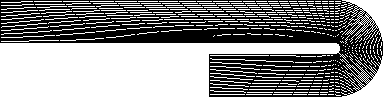
Figure 4.26: A typical grid, 50x30 cells
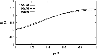
Figure 4.27: Grid refinement test for U-bend (velocity profiles)
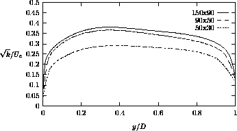
Figure 4.28: Grid refinement test for U-bend (turbulence intensity profiles)
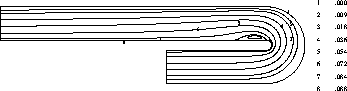
Figure 4.29: Streamlines for flow through U-bend
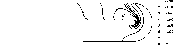
Figure 4.30: Isobars for flow through U-bend
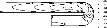
Figure 4.31: Turbulence intensity  for flow through U-bend
behaviour and also indicate that the length of the recirculation zone is about one duct width. The isobars shows also the qualitatively correct behaviour: high pressure in the impingement region, low pressure in the recirculation region and pressure recovery after separation. Also expected is the build up of turbulence intensity from the walls, especially in the impingement region.
The results of the computations are compared with the predictions obtained
by Bo et al. (1993) and the measurements taken from [Bo and Iacovides, 1993].
Bo et al. performed 3D calculations on orthogonal grids. Present results will
be compared with their results at the symmetry plane. They used the standard
k- model, whereas a k-l model is used in the near-wall regions instead
of wall functions. Furthermore, they employed two convection schemes: the hybrid
central/upwind scheme and a blended scheme, called LODA
[Zhou and Leschziner, 1988], in which the convective transport is approximated by
a combination of the well-known QUICK and first
model, whereas a k-l model is used in the near-wall regions instead
of wall functions. Furthermore, they employed two convection schemes: the hybrid
central/upwind scheme and a blended scheme, called LODA
[Zhou and Leschziner, 1988], in which the convective transport is approximated by
a combination of the well-known QUICK and first
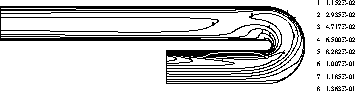
Figure 4.32: Length scales  for flow through U-bend
order upwind schemes. Blending of these two schemes is determined by a so-called
blending factor which is generally unknown. Hence, an iterative procedure is
needed in order to determine the blending factor. Another disadvantage of this
blending technique is that several measures are introduced to improve numerical
stability and to prevent negative values of k and  [Bo et al., 1993].
Therefore, one may expected that this blending technique is very costly.
[Bo et al., 1993].
Therefore, one may expected that this blending technique is very costly.
In Figures 4.33, 4.34, 4.35 and 4.36 the
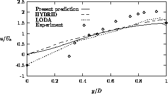
Figure 4.33: Streamwise velocity at 1D downstream of the bend
streamwise velocity and the turbulence intensity profiles are presented at 1D and 3D downstream of the bend. "LODA" means that the LODA scheme is employed on both momentum and turbulence equations on a 133x67x35 grid, whereas "HYBRID" denotes the application of the hybrid scheme on both momentum and turbulence equations on a 177x77x35 grid. With respect to our computations, the following conclusions may be drawn. At 1D downstream of the bend, the velocity is reasonably well predicted, although the recirculation length is underpredicted. There is no qualitative accordance between the prediction and measurements of the streamwise velocity at 3D downstream of the bend. Furthermore, at 1D downstream of the bend, the turbulence intensity near the inner side of the duct is predicted very well, while the turbulence level near the outer wall is overestimated. Finally, at 3D downstream of the bend, the
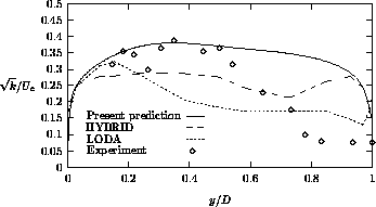
Figure 4.34: Turbulence intensity at 1D downstream of the bend
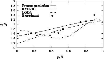
Figure 4.35: Streamwise velocity at 3D downstream of the bend
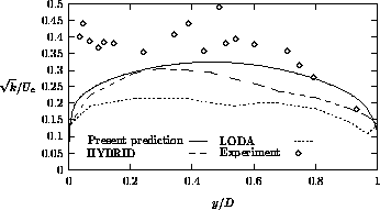
Figure 4.36: Turbulence intensity at 3D downstream of the bend
turbulence intensity is somewhat lower than the measured one.
Overall, the standard k- model does not produce accurate solutions,
because this model is not capable of predicting effects of curvature on the
turbulence. But there is qualitative agreement between computation and experiment,
and satisfactory agreement between the HYBRID scheme of Bo et al. and the
present computations.
model does not produce accurate solutions,
because this model is not capable of predicting effects of curvature on the
turbulence. But there is qualitative agreement between computation and experiment,
and satisfactory agreement between the HYBRID scheme of Bo et al. and the
present computations.