It is a well-known fact that integrating of the k- ![]() type models through
the near-wall
region and applying the no-slip condition yields unsatisfactory results. A
way to overcome this deficiency is to introduce damping effects, resulting in a
low-Reynolds-number form of these models, as outlined in the previous section. An
alternative and
still widely employed approach is the use of so-called wall functions, which model
the near-wall region. Wall functions use empirical laws to circumvent the
inability of the k-
type models through
the near-wall
region and applying the no-slip condition yields unsatisfactory results. A
way to overcome this deficiency is to introduce damping effects, resulting in a
low-Reynolds-number form of these models, as outlined in the previous section. An
alternative and
still widely employed approach is the use of so-called wall functions, which model
the near-wall region. Wall functions use empirical laws to circumvent the
inability of the k- ![]() model to predict a logarithmic velocity profile near a
wall. With these laws it is
possible to express the mean velocity parallel to the wall and
turbulence quantities outside the viscous sublayer in terms of the distance to
the wall and wall conditions such as wall shear stress, pressure gradient and
wall heat transfer.
Hence, the wall functions can be used to provide near-wall boundary conditions
for the momentum and turbulence transport equations, rather than conditions at
the wall
itself, so that the viscous sublayer does not have to be resolved and
the need for a very fine mesh is circumvented.
This method is proposed by Launder and Spalding [15].
model to predict a logarithmic velocity profile near a
wall. With these laws it is
possible to express the mean velocity parallel to the wall and
turbulence quantities outside the viscous sublayer in terms of the distance to
the wall and wall conditions such as wall shear stress, pressure gradient and
wall heat transfer.
Hence, the wall functions can be used to provide near-wall boundary conditions
for the momentum and turbulence transport equations, rather than conditions at
the wall
itself, so that the viscous sublayer does not have to be resolved and
the need for a very fine mesh is circumvented.
This method is proposed by Launder and Spalding [15].
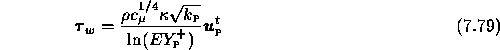
The wall function method can be summarized as follows. The near-wall flow is
modeled as a steady Couette flow. Experimental and dimensional analysis
shows that the wall shear stress ![]() is related
to the mean
velocity parallel to the wall through the so-called
logarithmic law of the wall:
is related
to the mean
velocity parallel to the wall through the so-called
logarithmic law of the wall:
where the wall-coordinate ![]() is given by
is given by
Here, ![]() is the tangential velocity vector,
is the tangential velocity vector,
![]() is the Von Kármán constant (
is the Von Kármán constant ( ![]() 0.4) and E is a
roughness parameter, approximately equal to 9.0 for a smooth wall.
The subscript P refers to the center of a cell adjacent to the wall.
The location of the cell center away from the wall must be such that
0.4) and E is a
roughness parameter, approximately equal to 9.0 for a smooth wall.
The subscript P refers to the center of a cell adjacent to the wall.
The location of the cell center away from the wall must be such that
![]() for the wall law (7.79) to be valid.
Otherwise, it is calculated from the viscous sublayer profile:
for the wall law (7.79) to be valid.
Otherwise, it is calculated from the viscous sublayer profile:
These relations are accurate only for two-dimensional near-wall turbulent flows where local equilibrium prevails, but we shall use them also in more general circumstances, for lack of anything better of comparable simplicity.
The wall shear stress ![]() can be employed as a
boundary condition for the momentum equations, as follows:
can be employed as a
boundary condition for the momentum equations, as follows:
so that the tangential stress
![]() is
prescribed. The second condition is assumed to be
is
prescribed. The second condition is assumed to be
![]()
The vector ![]() can be obtained by subtracting
the normal vector
can be obtained by subtracting
the normal vector ![]() from the velocity vector
from the velocity vector ![]() :
:
![]()
with
![]()
The contravariant velocity components
![]() and
and ![]() at cell centers are calculated by linear interpolations using
the neighbouring points.
The distance of a near-wall node P from a boundary surface can be found as the
scalar product of a vector connecting a boundary point B and P and the unit
normal vector
at cell centers are calculated by linear interpolations using
the neighbouring points.
The distance of a near-wall node P from a boundary surface can be found as the
scalar product of a vector connecting a boundary point B and P and the unit
normal vector ![]() (see Figure 7.17):
(see Figure 7.17):
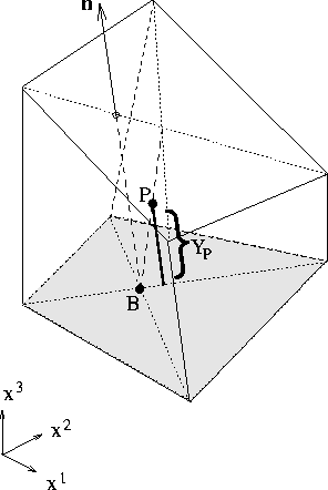
Figure 7.17: Calculation of normal distance ![]() between node P and boundary surface.
between node P and boundary surface.
![]()
The coordinates of B and P are obtained from the coordinates of cell vertices
by linear interpolations.
Remark: this method for the calculation of the normal wall distance is
particularly meant for three dimensions. For the two-dimensional case, we refer
to Section 6.3.3.
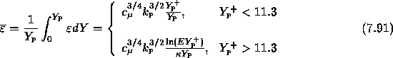
To ensure an accurate numerical representation of near-wall effects on the
turbulent energy, special care is needed in evaluating the
source terms in wall-adjacent cells. Let us consider the production term of the
equation for turbulent energy k. Because the near-wall flow is modeled
as steady Couette flow, the dominant contribution to the production is
![]()
Following Launder and Spalding [15], we assume that the local value of production at wall-adjacent cell center can be best obtained by averaging it over half of the near-wall cell:
assuming that ![]() is constant across the near-wall cell.
The dissipation rate of k in near-wall cells must be handled analogously.
To evaluate the dissipation rate in the logarithmic layer, we take
is constant across the near-wall cell.
The dissipation rate of k in near-wall cells must be handled analogously.
To evaluate the dissipation rate in the logarithmic layer, we take
assuming local equilibrium, consistent with the use of the logarithmic law of the wall. Within the viscous sublayer we adopt the following expression:
With (7.89) and (7.90) we can compute the average of the dissipation rate over half of the near-wall cell:
Here, we assume that the variation of turbulent energy across the near-wall
cell is negligible.
The expressions (7.88) and (7.91) replace ![]() and
and
![]() , respectively, which are source terms in the standard form of the equation
for turbulent energy (6.7).
Finally, the flux of turbulent energy through the wall is set to zero and,
instead of solving the equation for
, respectively, which are source terms in the standard form of the equation
for turbulent energy (6.7).
Finally, the flux of turbulent energy through the wall is set to zero and,
instead of solving the equation for ![]() , the
value of
, the
value of ![]() at the first grid point away from the wall is determined from
(7.89).
at the first grid point away from the wall is determined from
(7.89).
An important advantage of wall functions is that they allow inclusion of empirical
information for special cases, such as wall roughness, pressure gradients and mass
and heat transfer. Here, we shall discuss wall functions applicable to a
rough wall.
We consider a turbulent flow over rough surfaces. Let ![]() denote
the average height of roughness elements. We assume that the roughness has no
influence on the flow except near the wall, i.e.
denote
the average height of roughness elements. We assume that the roughness has no
influence on the flow except near the wall, i.e.
![]() where L is the characteristic length of the flow
geometry. Following Tennekes and Lumley [31], the law of the wall
for a rough wall is given by
where L is the characteristic length of the flow
geometry. Following Tennekes and Lumley [31], the law of the wall
for a rough wall is given by
Here,
![]() and
and ![]() is the roughness Reynolds number defined as
is the roughness Reynolds number defined as
![]()
A generalized form of the wall law (7.92) can be found with the aid of a one-equation model in which the transport equation is provided for the turbulent energy k:
This law of the wall (7.94) is preferable because it allows
non-equilibrium effects on the turbulent energy k.
If the roughness elements are submerged in the viscous sublayer then the
turbulence will not be affected by the roughness. In other words, the wall can be
considered as smooth. Thus, in the limit ![]() ,
we should have
,
we should have
![]()
On the other hand, Nikuradse (see [23]) found by means of
experiments that when the surface is very rough, i.e. for large values of
![]() , the function
, the function ![]() becomes independent
of
becomes independent
of ![]() , viz.,
, viz.,
![]()
If the roughness elements are submerged in the buffer layer (a transition region
between the viscous sublayer and the log layer), i.e.
![]() , then the function f depends on the roughness
Reynolds number. However, in many engineering calculations, the buffer layer is
ignored. Hence, the location of the edge of viscous sublayer and log layer is taken
equal to
, then the function f depends on the roughness
Reynolds number. However, in many engineering calculations, the buffer layer is
ignored. Hence, the location of the edge of viscous sublayer and log layer is taken
equal to ![]() , which value is obtained by simply linking the linear
velocity profile in the viscous sublayer to the logarithmic velocity profile
in the log layer. Thus, for
, which value is obtained by simply linking the linear
velocity profile in the viscous sublayer to the logarithmic velocity profile
in the log layer. Thus, for ![]() , the wall is considered
to be smooth, otherwise the wall is rough. The generalized law of the wall
for rough walls then becomes:
, the wall is considered
to be smooth, otherwise the wall is rough. The generalized law of the wall
for rough walls then becomes:
where ![]() . From this wall law the wall shear stress can be
computed, which can be used as boundary condition for the momentum equations
(see (7.82)).
. From this wall law the wall shear stress can be
computed, which can be used as boundary condition for the momentum equations
(see (7.82)).
The rapid variation of turbulence quantities also necessitates special measures in evaluating the production and dissipation rates of turbulent kinetic energy near the rough wall. The average production and dissipation rates used in the near-wall cells have the following form:
![]()