 should be
satisfied after discretization.
 in terms
of its contravariant components
  , and recomputing
 from
from  , the original vector field
 should be recovered exactly.
In discretizing the governing equations (2.8)-(2.12), the following requirements should be met for accuracy reasons:
 should be
satisfied after discretization.
 in terms
of its contravariant components
  , and recomputing
 from
from  , the original vector field
 should be recovered exactly.
 are chosen as unknowns. More details can be found
in [Mynett et al., 1991], [Wesseling et al., 1992] and
[Segal et al., 1992].
A finite volume method is used to discretize the governing equations on a
staggered grid in the computational rectangle G. In G we choose a uniform
grid, choosing the mapping  such that the mesh-size
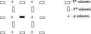
  . Figure 3.1 shows the
locations of the points for the velocities
  and pressure p in the
grid.

Figure 3.1: Arrangement of the unknowns for a staggered grid
The turbulence quantities k and  are evaluated at pressure points. For
brevity the momentum and k-
 equations are written in the following form:
where
and
where
Here,  and
and  represents the nonlinear source
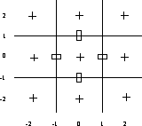
terms. For convenience we introduce the local cell coordinates given
by Figure 3.2.

Figure 3.2: Local cell coordinates
Discretization of the continuity equation is obtained by integration over a
finite volume  with center (0,0), using (2.5):

The momentum equation (3.1) is discretized in space as follows, taking
for example a  -cell with center at (1,0), using (2.6):
Integration of the momentum equation with  over a
  -cell with
center (0,1) is done similarly.
Using (2.5), the transport equation (3.3) is integrated over a pressure cell with center (0,0) which yields
The right-hand sides of (3.1) and (3.3) are integrated using midpoint rules:

and

with  if
if  or
or  if
if  .
.
The discretization is completed by substituting (3.2) in
(3.6) and (3.4) in (3.7). Furthermore,
 is replaced by
  . The cell-face fluxes containing
cell-face values (convection) and derivatives (diffusion) have to be approximated.
Central differences will be employed, except for the convection of turbulence
equations in which a hybrid central/upwind scheme [Spalding, 1972] will be
adopted. The reason for this is as follows. The k-
 equations are highly
nonlinear and coupled. As a consequence, the computational task is complicated,
because numerical experiments have shown that the convergence of iterative
methods, to solve this coupled nonlinear problem, is adversely affected by
negative values of k and
  which occur when convection is approximated
by a non-positive (e.g. central) scheme. Using the hybrid scheme, the
approximation of the face value
  at point (1,0), for example, is given by

where  and
and  are given by


Furthermore, the mesh-Péclet number  is defined by
If  , a first order upwind scheme is used, otherwise a
switch to central differences is applied. The switching function
  is
defined as

Non-orthogonal coordinates introduce mixed derivatives in diffusion terms, which make the scheme non-positive even when upwind discretization is applied. Many authors (e.g. Rhie and Chow (1983), Demirdzic et al. (1987) and Melaaen (1991)) treat these derivatives in an explicit manner, i.e. calculating them from values obtained in the previous iteration, but we found that our iterative solver allows to treat the mixed derivatives implicitly. Nonetheless, in some circumstances (highly non-orthogonal grid or large non-alignment of grid lines and streamlines) this scheme may produce numerical instability. In such cases certain precautions will have to be taken; for a discussion see [Zijlema, 1993].
The discretization of the production of turbulent energy (2.13) is carried
out by substituting (2.4) in (2.13) and with central differencing.
Again,  is replaced by
  . In spite of the presence of
Christoffel symbols numerical experiments have shown that this discretization
gives good results on reasonable smooth grids.
The discretization of the  -momentum equation results in the 19-point stencil
presented in Figure 3.3.

Figure 3.3: Stencil for  -momentum equation
The  stencil is obtained by rotation over
  . The total number of
variables linked together in the transport equation is 9.
Implementation of boundary conditions for the momentum and transport equations is discussed in [Segal et al., 1992] and [Zijlema, 1993]. Also discussion about the implementation of periodic as well as antiperiodic boundary conditions in our code can be found in [Segal et al., 1993].