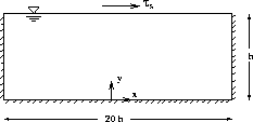
Figure 4.1: The domain for the driven cavity flow (not to scale)
The calculation of a driven cavity flow shown in Figure 4.1 is compared

Figure 4.1: The domain for the driven cavity flow (not to scale)
with the experiments of Baines and Knapp (1965). Furthermore, experimental data for the velocity along the vertical plane in the middle of the cavity are taken from [Rodi, 1984].
At walls, the wall functions are applied. At the moving wall the experimental
surface shear stress  is given. In order to reduce the turbulence length
scale near the moving wall, the following boundary conditions for k and
  are used:

where  is the surface friction velocity and
y is the distance perpendicular to the moving wall. The Reynolds number based on
the surface friction velocity and the depth h of the cavity is approximately
6,000.
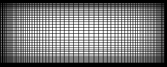
Figure 4.2 shows the 80x50 mesh in which the grid cells are highly

Figure 4.2: Grid used for prediction of flow in driven cavity (not to scale)
stretched in order to resolve the steep velocity gradients near the walls.
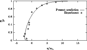
The predicted normalized velocity profile along the vertical plane in the middle of the cavity is shown and compared with the experimental data in Figure 4.3.

Figure 4.3: Streamwise velocity profile at  m
m
It is seen that the calculation is in very good agreement with the measurements.
Hence, it may be concluded that this type of flows are well described by the
standard k- model. Furthermore, our general coordinate discretization is
accurate on the non-uniform grid of Figure 4.2. Convergence of the
preconditioned GMRES method was not adversely affected by the high (up to 10) mesh
aspect ratios which occur.