


Next: Turbulent flow through
Up: Results
Previous: Driven cavity flow
Turbulent flow over a backward facing step is a widely used benchmark problem to
evaluate the performance of turbulence models in the prediction of separated
flows. It is well-known that the standard k- model with wall functions
underpredicts the reattachment length in the backward facing step by an amount in
the order of 20-25%. This has been widely discussed since the 1980-81 AFOSR-HTTM
Stanford Conference on Complex Turbulent Flows, see e.g. [Demirdzic, 1982],
[Nallasamy, 1987] and [Thangam and Speziale, 1991].
In this section we present some results. For the computations the flow
configuration of [Kim et al., 1980] (which was one of the test cases in the
aforementioned conference) has been selected. In this case the ratio of step
height to outlet channel height is 1:3 and the Reynolds number based on the step
height and  is 44,000. The domain is sketched in Figure 4.4.
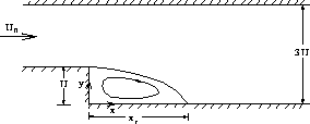
Figure 4.4: Geometry of the backward facing step flow
Inlet profiles for velocities and turbulence quantities are specified at 4
step heights upstream of the step corner. These profiles are obtained from
a preliminary calculation of a fully developed turbulent flow in a straight
channel for the given Reynolds number. Wall functions are used at the upper and
lower walls and outstream conditions (i.e. normal stress and tangential velocity
are zero and zero normal gradient conditions for turbulence quantities) are
applied 30 step heights downstream of the step.
Figure 4.5 shows a part of the non-orthogonal 40x94 mesh employed.
Overall, the mesh is smooth except near the step. In fact, the backward facing
step problem is suited for a multiblock approach in which an orthogonal
coordinate system can be employed. However, our purpose is to test our general
coordinates discretization. Inaccuracies will occur with the present grid, which
will be shown later. An initial calculation with a 20x45 grid indicates little
change in the reattachment length compared to the result from the 40x94 grid.
Hence, further grid refinement seems unnecessary.
In Figure 4.6 the computed streamlines are shown. The calculated
reattachment
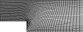
Figure 4.5: A part of the 40x94 grid for the backward facing step flow

Figure 4.6: Predicted streamlines for flow over the backward facing step
length is  , which gives 24%
underprediction of the experimental reattachment length of
  . This
result resembles the results found earlier at the aformentioned conference very
well. Plots of calculated isobars, turbulence intensity (defined as
 ) and turbulence length scale (defined as
  )
are shown in Figure 4.7.
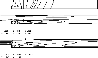
Figure 4.7: Predicted features of turbulent flow over the backward facing step:
isobars, turbulence intensity and length scales, respectively
Profiles of the normalized streamwise velocity are given in Figures 4.8,
4.9 and 4.10 and are compared with the experimental data.
As can be seen, there is reason-ably good agreement between the computations and
the experimental results and
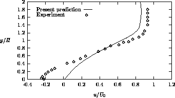
Figure 4.8: Streamwise velocity profile at 
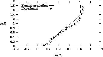
Figure 4.9: Streamwise velocity profile at 
discrepancies are mainly due to the underprediction of the reattachment
length. Furthermore, profiles of the normalized Reynolds shear stress are
presented in Figures 4.11, 4.12 and 4.13. Deficiencies occur
near the recirculation zone, where the shear stress peaks are underpredicted,
whereas in the recovery region far downstream of the reattachment the shear
stress is reasonably well predicted. The results and their deficiencies
are typical of k- modeling. The results obtained with the present
method are in very good agreement with the computations of Demirdzic (1982).
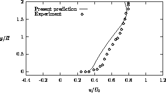
Figure 4.10: Streamwise velocity profile at 
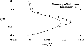
Figure 4.11: Shear stress profile at 
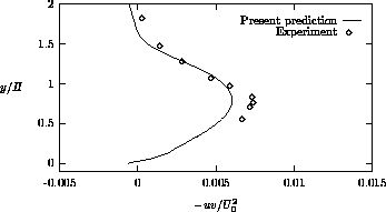
Figure 4.12: Shear stress profile at 
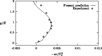
Figure 4.13: Shear stress profile at 
From Figure 4.14 it is seen that small wiggles occur in the streamlines due
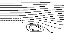
Figure 4.14: Wiggles in streamlines for turbulent flow over backward facing step
to the non-smoothness of the grid near the step. Although undesirable these
wiggles seem to have a very small influence on the solutions, and thus are not
too dramatic. As mentioned before, a multiblock approach combined with Cartesian
grids is a natural approach to avoid this problem. This can be demonstrated with
a computation of laminar flow over a backward facing step with Re = 300. It is
concluded from Figures 4.15 and 4.16 that better results are

Figure 4.15: Inaccurate streamlines for Re = 300 with a non-smooth grid

Figure 4.16: Accurate streamlines for Re = 300 with an orthogonal grid computed with multiblock
obtained with the multiblock method. For more details on the multiblock method,
we refer to [Brakkee and Wilders, 1994].
A way to improve the single block results would be by further smoothing of the
discontinuity in the grid.


Next: Turbulent flow through
Up: Results
Previous: Driven cavity flow
ISNaS ontwikkeling
Fri May 26 14:01:30 METDST 1995
 model with wall functions
underpredicts the reattachment length in the backward facing step by an amount in
the order of 20-25%. This has been widely discussed since the 1980-81 AFOSR-HTTM
Stanford Conference on Complex Turbulent Flows, see e.g. [Demirdzic, 1982],
[Nallasamy, 1987] and [Thangam and Speziale, 1991].
 is 44,000. The domain is sketched in Figure


 , which gives 24%
underprediction of the experimental reattachment length of
  . This
result resembles the results found earlier at the aformentioned conference very
well. Plots of calculated isobars, turbulence intensity (defined as
 ) and turbulence length scale (defined as
  )
are shown in Figure


 modeling. The results obtained with the present
method are in very good agreement with the computations of Demirdzic (1982).


